Useful Summary: An engineer needs to know how to keep their solution times ACCURATE and FAST to solve challenging problems.

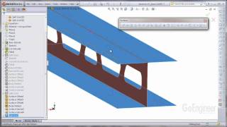
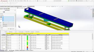
Solidworks Shell Element Simulation Surface Model Simulation - Information Core Points

This discovery page summarizes Solidworks Shell Element Simulation Surface Model Simulation through meaning, examples, related intent, useful checks, and follow-up paths so readers can continue into related pages with clearer context.

In addition, this page also connects Solidworks Shell Element Simulation Surface Model Simulation with for broader topic coverage.

Information Core Points

Important details can vary by source, so this page groups the most readable points into a scannable format.

Reference What It Connects To

This part keeps Solidworks Shell Element Simulation Surface Model Simulation connected to practical references instead of leaving it as a single isolated phrase.

Guide Search Overview

Solidworks Shell Element Simulation Surface Model Simulation can be reviewed through a clear overview first, then compared with related entries and supporting context.

Information Useful Reminders

Use the related entries as follow-up paths when you need more examples, current details, or alternative wording.

Relevant points collected here

  • An engineer needs to know how to keep their solution times ACCURATE and FAST to solve challenging problems.

What this page helps clarify

This format works because it offers a simple summary for Solidworks Shell Element Simulation Surface Model Simulation so they can continue with better search intent.

Sponsored

Questions People Also Check

How does Solidworks Shell Element Simulation Surface Model Simulation connect to topic?

Solidworks Shell Element Simulation Surface Model Simulation can connect to topic when readers need context, examples, comparisons, or practical next steps inside the same topic area.

How does Solidworks Shell Element Simulation Surface Model Simulation connect to overview?

Solidworks Shell Element Simulation Surface Model Simulation can connect to overview when readers need context, examples, comparisons, or practical next steps inside the same topic area.

How can readers check Solidworks Shell Element Simulation Surface Model Simulation more carefully?

Check freshness, source quality, related examples, and any requirements or limitations before relying on one answer.

How should beginners approach Solidworks Shell Element Simulation Surface Model Simulation?

Beginners should scan the overview first, then use related terms to narrow the subject into a more specific question.

Picture References

Solidworks shell element simulation [Surface model simulation]
SIMULATION TUTORIAL: 3 ways to create Shell Elements in SOLIDWORKS Simulation
SolidWorks Simulation 2013 - Shell Thickness Display
Sheet Metal Analysis in SolidWorks (shell element definition) | Step-by-step  Simulation Tutorial
SOLIDWORKS Simulation - Shell Elements for Frames Tutorial
Why SolidWorks Simulation - Automatic creation of Shell, beam and Solid elements
Why SolidWorks Simulation - Easy handling of large models that need to represented by Shell elements
SolidWorks Simulation - Use of Symmetry with Shell Elements
Part 1: SOLIDWORKS Simulation | Convergence | Finite Element Analysis (FEA) | Meshing
Solidworks simulation | Linear static analysis of a shell model
Sponsored
Read the Notes
Solidworks shell element simulation [Surface model simulation]

Solidworks shell element simulation [Surface model simulation]

Read more details and related context about Solidworks shell element simulation [Surface model simulation].

SIMULATION TUTORIAL: 3 ways to create Shell Elements in SOLIDWORKS Simulation

SIMULATION TUTORIAL: 3 ways to create Shell Elements in SOLIDWORKS Simulation

Read more details and related context about SIMULATION TUTORIAL: 3 ways to create Shell Elements in SOLIDWORKS Simulation.

SolidWorks Simulation 2013 - Shell Thickness Display

SolidWorks Simulation 2013 - Shell Thickness Display

Read more details and related context about SolidWorks Simulation 2013 - Shell Thickness Display.

Sheet Metal Analysis in SolidWorks (shell element definition) | Step-by-step  Simulation Tutorial

Sheet Metal Analysis in SolidWorks (shell element definition) | Step-by-step Simulation Tutorial

Read more details and related context about Sheet Metal Analysis in SolidWorks (shell element definition) | Step-by-step Simulation Tutorial.

SOLIDWORKS Simulation - Shell Elements for Frames Tutorial

SOLIDWORKS Simulation - Shell Elements for Frames Tutorial

Read more details and related context about SOLIDWORKS Simulation - Shell Elements for Frames Tutorial.

Why SolidWorks Simulation - Automatic creation of Shell, beam and Solid elements

Why SolidWorks Simulation - Automatic creation of Shell, beam and Solid elements

Read more details and related context about Why SolidWorks Simulation - Automatic creation of Shell, beam and Solid elements.

Why SolidWorks Simulation - Easy handling of large models that need to represented by Shell elements

Why SolidWorks Simulation - Easy handling of large models that need to represented by Shell elements

Read more details and related context about Why SolidWorks Simulation - Easy handling of large models that need to represented by Shell elements.

SolidWorks Simulation - Use of Symmetry with Shell Elements

SolidWorks Simulation - Use of Symmetry with Shell Elements

Read more details and related context about SolidWorks Simulation - Use of Symmetry with Shell Elements.

Part 1: SOLIDWORKS Simulation | Convergence | Finite Element Analysis (FEA) | Meshing

Part 1: SOLIDWORKS Simulation | Convergence | Finite Element Analysis (FEA) | Meshing

An engineer needs to know how to keep their solution times ACCURATE and FAST to solve challenging problems. Accuracy of ...

Solidworks simulation | Linear static analysis of a shell model

Solidworks simulation | Linear static analysis of a shell model

Read more details and related context about Solidworks simulation | Linear static analysis of a shell model.